How to Choose VTOL Propellers?

Selecting optimal propellers for Vertical Takeoff and Landing (VTOL) aircraft requires balancing competing demands across multiple flight regimes. Unlike conventional aircraft that optimize for single-phase flight, VTOL platforms must perform efficiently in hover, transition, and cruise phases with fundamentally different aerodynamic requirements. This guide provides practical, engineering-focused methodology for propeller selection across common VTOL architectures.
Define Mission & Architecture
VTOL Architecture Classification
Modern VTOL platforms typically employ three primary configurations. Lift + Cruise systems use dedicated vertical lift propellers for hover and separate pusher/puller propellers for forward flight. Tilt-rotor designs rotate the same propellers between vertical and horizontal orientations. Multirotor VTOL configurations extend traditional quadcopter designs with additional forward-thrust capability.
Propeller Role Specialization
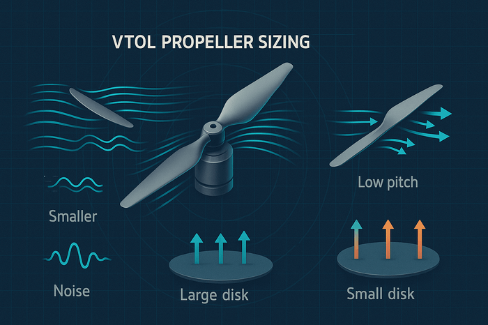
In Lift + Cruise architectures, lift propellers optimize for static thrust generation and low-speed efficiency during hover and transition phases. These typically feature larger diameters and lower pitch angles. Cruise propellers prioritize forward-flight efficiency and high-speed performance, using higher pitch ratios and smaller diameters optimized for translational flight.
Mission Driver Analysis
Critical parameters include Maximum Takeoff Weight (MTOW), payload capacity, operational altitude, noise constraints, and endurance requirements. Industry Lift+Cruise reference designs demonstrate typical parameter conflicts: 8×lift propellers provide vertical thrust capability, while 1×pusher propeller handles cruise efficiency in the 6,000-pound weight class.
Design Separation Rationale
Parameter conflicts between lift and cruise optimization make role separation mainstream for practical VTOL design. Attempting to optimize single propellers for both regimes typically results in compromised performance in all flight phases.
10-Minute Rules for Diameter / Pitch / Disk Loading

Diameter and Efficiency Relationship
Larger diameter propellers operating at lower RPM typically achieve higher efficiency and reduced noise signatures. However, space constraints, contrarotating requirements, and coaxial configurations may limit diameter selection. Disk loading (thrust divided by propeller disk area) directly impacts hover power requirements—lower disk loading reduces power consumption but requires larger propellers.
Pitch Selection Guidelines
Pitch represents the theoretical advance distance per revolution in undisturbed air. For cruise propellers, optimize based on advance ratio J=V/(nD) to maintain blade sections at efficient angles of attack (typically 2-5° for high L/D operation). Excessive pitch causes blade stall and motor overloading, while insufficient pitch limits thrust generation and reduces efficiency.
Practical Sizing Rules
For initial sizing: hover disk loading should target 3.5-12 lb/ft² for efficiency and noise optimization, 12-20 lb/ft² for more compact designs requiring higher power density. Tip speed should target approximately 550 ft/s (industry best practice) for urban noise constraints; 0.7 Mach equals 781 ft/s at sea level, which typically exceeds noise optimization targets.
Materials & Blade Count
Material Selection Strategy
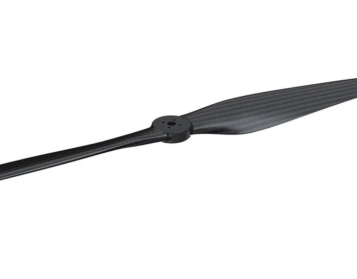
Polymer + Carbon Fiber composites balance strength, weight, and cost for heavy-lift propellers. These hybrid materials provide adequate stiffness while maintaining repairability and cost-effectiveness. Full carbon fiber construction offers higher stiffness and reduced weight but exhibits lower impact resistance and ductility compared to hybrid composites, particularly under low-speed impact conditions.
Blade Count Trade-offs
Additional blades can increase disk loading when diameter is constrained and may help reduce certain tonal noise frequencies through better load distribution. Two-blade configurations maximize efficiency for endurance applications. Three-blade and higher counts improve thrust density and response but require careful design to optimize efficiency and noise characteristics.
Folding Propeller Considerations
Folding propellers significantly reduce cruise drag when not actively generating thrust, as demonstrated in advanced aerospace research on conforming folding propeller designs. Critical considerations include hub compatibility, folding mechanism reliability under various environmental conditions (temperature, vibration), and maintenance requirements for hinge mechanisms and retention systems.
Interfaces & Compatibility
Mounting System Requirements
Verify hub bore diameter, bolt circle patterns, shaft mounting interfaces, and T-mount adapter compatibility. Spinner and hub systems must accommodate both clockwise (CW) and counterclockwise (CCW) rotation pairs for balanced torque management.
Installation Critical Points
Proper torque specifications, reverse-thread applications, and threadlocker requirements prevent catastrophic propeller loss. Dynamic balance becomes critical at high RPM operation. Contrarotating and coaxial installations require precise CW/CCW pairing and careful clearance management.
Transition Flight Validation
Engineering changes require comprehensive transition testing progression: bench testing → hover validation → transition phase → cruise verification. Each phase validates different performance parameters and identifies potential failure modes.
Selection by Application
Multirotor VTOL Applications
Separate lift and cruise propeller configurations offer maximum performance optimization for each flight phase. Lift propellers prioritize vertical thrust efficiency with moderate pitch angles, while cruise propellers feature higher pitch for forward flight efficiency. This architecture suits logistics delivery, aerial mapping, and inspection missions requiring extended cruise ranges.
Tilt-rotor/Tilt-wing Systems
Single propeller sets that rotate between vertical and horizontal orientations require compromise designs balancing hover and cruise performance. The propeller must provide adequate vertical thrust while maintaining reasonable forward flight efficiency. Best suited for smaller platforms where mechanical complexity is acceptable for payload space optimization.
Heavy-lift VTOL Operations
Large payload requirements demand maximum static thrust generation with emphasis on low disk loading for power efficiency. Propellers typically feature larger diameters and moderate pitch angles to minimize power consumption during hover phases. Applications include cargo transport, construction support, and industrial heavy-lift missions.
Long-endurance Survey Missions
Efficiency optimization across all flight phases maximizes mission duration and coverage area. Propeller selection emphasizes low power consumption with balanced thrust and cruise performance. Two-blade configurations minimize drag and maximize battery life for mapping, surveillance, and environmental monitoring applications.
Urban/Low-noise Requirements
Noise reduction takes priority over maximum performance, requiring lower tip speeds and careful blade design. Propellers feature moderate dimensions with optimized blade shapes to minimize acoustic signature while maintaining adequate thrust. Essential for urban air mobility, emergency services, and noise-sensitive commercial operations.
Example Configurations
Package A: 5-8 kg MTOW Logistics Scout (4 Lift + 1 Cruise)
Configuration Overview: Four lift propellers provide 12-15 kg total thrust capacity (minimum 2:1 thrust-to-weight ratio for control authority), single pusher propeller handles cruise efficiency.
Propeller Selection: Lift propellers approximately 22" × 7.4" diameter/pitch combination, cruise propeller 16" × 12" for forward flight efficiency. [Assumption → validate through bench testing: current consumption, thermal margins, noise characteristics].
Sizing Logic: Target 10 lb/ft² disk loading for lift propellers provides efficient hover capability. For 22" propellers targeting 550 ft/s tip speed, optimal operation occurs around 5,700-6,000 RPM. Higher RPM increases noise and power penalties. ESC current capacity requires 20-30% headroom above calculated peak current draw.
Validation Protocol: Bench testing validates current consumption and thermal performance. Transition testing verifies control authority during conversion from hover to forward flight. Cruise validation confirms efficiency targets and endurance requirements.
Risk Mitigation: Monitor for stall conditions during aggressive transitions. Thermal management prevents motor overheating during extended hover operations. Torque limits prevent drivetrain damage under high-load conditions.
Package B: 10-15 kg Mapping at ~3,000 m Altitude
High-Altitude Considerations: Air density at 3,000 meters is approximately 74% of sea level, requiring 30-40% increase in propeller capability (larger diameter, higher RPM, or increased power) for equivalent thrust performance. Larger diameter, lower RPM propellers help maintain efficiency in reduced density conditions.
Propeller Specifications: Lift propellers scale to 26-30" × 8-10" to compensate for altitude performance degradation. [Reference → validate with high-altitude performance data for specific motor combinations].
Power System Scaling: Battery capacity increases 20-25% to maintain endurance targets. ESC thermal derating accounts for reduced cooling effectiveness at altitude. Motor efficiency curves shift due to reduced air density cooling.
Mission Profile Optimization: Extended cruise phases at altitude favor higher-pitch cruise propellers. Climb rate limitations may require mission profile adjustments to prevent thermal overload during ascent phases.
Package C: 20-30 kg Industrial Inspection (Long Cruise)
Heavy-Lift Requirements: Total thrust capacity targets 50-60 kg (minimum 2:1 thrust-to-weight ratio) for adequate control margins during gusty conditions and payload variations.
Propeller Configuration: Lift propellers 30" × 12" or 34" × 13.6" class for maximum static thrust generation. Low-RPM, large-diameter cruise propeller optimizes for long-duration forward flight. [Validate with structural load analysis and motor torque specifications].
Structural Considerations: Frame stiffness becomes critical with large-diameter propellers. Landing gear clearance must accommodate propeller ground clearance requirements. Transportation constraints may necessitate folding propeller designs.
Safety Systems: Redundant motor systems for critical lift propellers. Emergency landing protocols account for single-propeller failure scenarios. Maintenance scheduling addresses higher wear rates from extended operation cycles.
Common Pitfalls and How to Avoid
Over-Propping Consequences
Excessive propeller size causes over-current conditions, brownout situations, and thermal runaway in motors and ESCs. Validate current consumption across full throttle range during bench testing before flight operations.
Interface Mismatches
Incorrect hub bore, bolt patterns, or shaft interfaces cause catastrophic failures. Maintain detailed compatibility matrices for motor-propeller combinations. Verify CW/CCW pairing prevents control reversal and torque imbalance.
Clearance and Dynamic Issues
Insufficient clearance between propellers and frame structures, boom assemblies, or landing gear causes damage during transition maneuvers. Transition dynamics may cause temporary propeller deflection requiring additional clearance margins.
Balance and Vibration Problems
Under-balanced propellers create vibration affecting IMU accuracy and structural integrity. Dynamic balancing becomes critical for large-diameter, high-RPM applications. Mismatched propeller pairs in coaxial configurations amplify vibration issues.
Key Design Formulas
Essential Calculations for VTOL Propeller Selection:
- Disk Loading: DL = T/A (T = thrust, A = propeller disk area)
- Tip Speed: V_tip = π × D × n / 60 (D = diameter in ft, n = RPM)
- Advance Ratio: J = V/(n × D) (V = flight speed)
Example: For a 22" propeller targeting 550 ft/s tip speed: n = 550 × 60 / (π × 1.83) ≈ 5,730 RPM
VTOL Propeller Selection Checklist
Define architecture and MTOW requirements; calculate thrust margins for hover and climb phases (minimum 2:1 thrust-to-weight ratio)
Establish cruise power and endurance targets; determine efficiency requirements for mission completion
Match motor KV × voltage × diameter/pitch combinations; ensure ESC current headroom of 20-30% above peak calculated loads
Verify hub bore, bolt circle, and shaft compatibility; confirm CW/CCW pairing for balanced torque management
Check physical clearance from booms, nacelles, and ground contact; target tip speed around 550 ft/s for optimal noise control
Balance all propellers before installation; apply proper torque specifications and threadlocker according to manufacturer requirements
Log baseline current and temperature during initial test flights; establish performance monitoring protocols
For folding designs: verify hub hinge specifications and establish maintenance intervals for mechanical components
Conduct systematic validation: bench → hover → transition → cruise testing progression with performance documentation
Establish emergency procedures for propeller failure scenarios and maintenance scheduling based on operational hours and conditions
Recommended VTOL Propeller

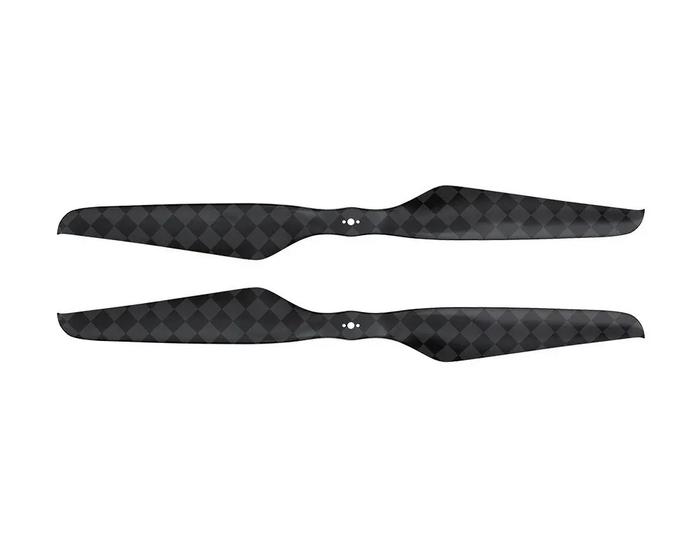
The following table compares LIGPOWER V Series VTOL propellers to help you select the optimal propeller for your specific application requirements:
All propellers feature Polymer+CF construction and operate from -40℃ to 65℃
The V Series progression provides clear upgrade paths based on thrust requirements. For lightweight surveillance drones, the V187.2 offers excellent efficiency. Medium payload applications benefit from the V227.4 to V3012 range, while heavy-lift industrial missions require the V3413.6 or V40*16 models.
VTOL Propeller Frequently Asked Questions
The following addresses common questions about VTOL propeller selection, installation, and performance optimization:
What makes VTOL propellers different from standard multirotor propellers?
VTOL propellers feature enlarged pitch angles and optimized blade geometry specifically designed for dual-mode flight operations. They provide up to 10% more thrust than comparable multirotor propellers and offer 8% faster response times during critical transition phases. The enhanced blade root construction provides additional safety margins during high-stress vertical operations.
How do I determine the correct propeller size for my VTOL aircraft?
Calculate your aircraft's maximum take-off weight and target thrust-to-weight ratio (typically 2:1 as baseline for adequate control authority and wind resistance). Match this requirement to the recommended thrust range in our product specifications. Consider your motor's power capabilities and ensure the propeller's maximum RPM limits align with your motor's specifications.
Can LIGPOWER V Series propellers operate in extreme temperature conditions?
Yes, all V Series VTOL propellers are rated for operation from -40℃ to 65℃ (propeller body specification), making them suitable for arctic conditions, desert environments, and high-altitude operations. The polymer-carbon fiber composite construction maintains structural integrity across this temperature range. Note: System integration requires verifying motor, ESC, and battery temperature ratings separately.
What is the expected lifespan of VTOL propellers under normal operating conditions?
LIGPOWER V Series propellers are designed for extended operational life under professional use conditions. Lifespan depends on flight hours, operating environment, and maintenance practices. Regular inspection for damage, proper storage, and avoiding over-stress conditions will maximize propeller longevity. Replace propellers showing signs of fatigue, damage, or performance degradation.
How do VTOL propellers affect battery life and flight time?
With proper motor/ESC/operating condition matching, V Series propellers may demonstrate improved thrust-per-amp ratios in hover or cruise segments. Efficiency benefits should be verified through bench testing (thrust-current-RPM curves) and flight testing to confirm actual performance gains for your specific system configuration.
Are special balancing procedures required for VTOL propellers?
V Series propellers are factory-balanced using ISO 1940/ISO 21940 standard methods. Allowable residual unbalance depends on rotational speed and rotor mass. After impact or extended operation, field verification with a propeller balancer is recommended to maintain optimal performance and minimize vibration.
What motor compatibility considerations apply to VTOL propellers?
Ensure your motor's KV rating, power output, and RPM limits are compatible with the propeller specifications. Note: V Series propellers are currently not compatible with T-MOTOR Quick-Attach-Detach adapters (manufacturer specification). Verify hub bore diameter and mounting interfaces before selection. VTOL operations require motors capable of handling variable loads during transition phases.
How do altitude and temperature affect VTOL propeller performance?
While propellers operate within -40℃ to 65℃ temperature range, air density reduction significantly affects performance. At 3,000 meters altitude, air density is approximately 0.91 kg/m³ (versus 1.225 kg/m³ at sea level), increasing hover power requirements and affecting cooling efficiency. High-altitude missions require thrust-current-RPM verification and thermal margin analysis to prevent overheating during extended operations.


